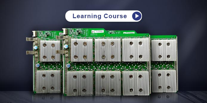
- Innosilicon maintenance courses mainly include basic theoretical knowledge and troubleshooting demonstrations of Innosilicon hash board repair, including Innosilicon T1 hash board repair, T2 hash board repair, T2TH+ hash board repair, and will also provide correct hash board repair guide. Each video will explain the troubleshooting ideas for Innosilicon hash board failures.
-
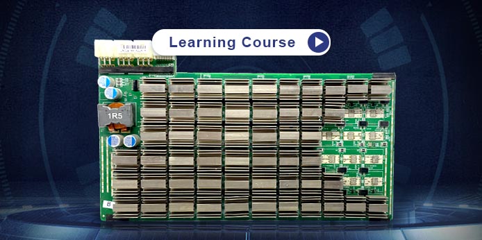
Innosilicon T1 hash board repair tutorial
Date: 2022-11-09 -
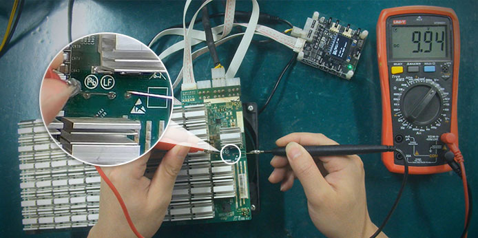
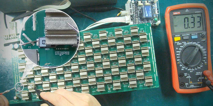
Innosilicon T1 main powering unit voltage measurement method
Date: 2023-02-22 -
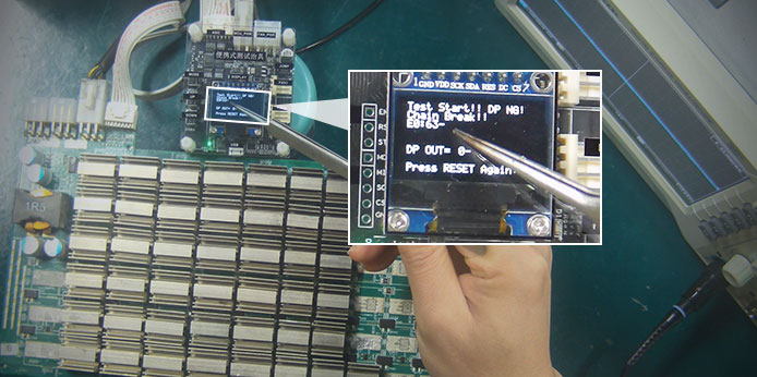
Innosilicon T1 hash board troubleshooting for report a specific chip number
Date: 2023-04-12 -
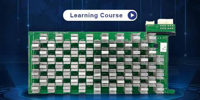
Innosilicon T2 hash board repair tutorial basics
Date: 2022-11-09 -
Innosilicon T2 hashboard main powering unit voltage measurement method
Date: 2023-02-27 -
Innosilicon T2TH plus hash board repair tutorial basics
Date: 2022-11-09 -
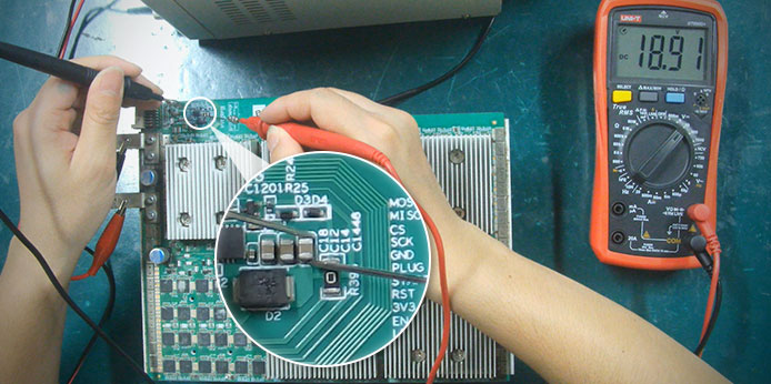
Innosilicon T2TH plus hashboard main powering unit voltage measurement method
Date: 2023-02-27
May Day Holiday Notice
CLOSE
Dear Friends,
Hello everyone, May 1-5, 2026 (GMT+8) are the May Day holidays in China. During this period, our customer support and course tutor teams may experience delays in responding to your inquiries.
We appreciate your patience and understanding. Normal response times will resume after the holiday.
Thank you for your continued support.
Best wishes,
ZEUS MINING CO., LTD.
CLOSE