Antminer S19 XP Hash Board Repair Guide
-
I. Maintenance Platform / Tool / Equipment Preparation Requirements
1. Platform requirements:
Anti-static repair workbench (the workbench needs to be grounded), the reapirman must wear anti-static wrist straps.
2. Equipment requirements:
(1) Constant temperature soldering iron (350C°-380C/662F°-716F), pointed iron head is used for soldering small chips such as chip resistors and capacitors.
(2) Heat gun and heating platform (350C-400C).
(3) BGA repair workbench is sui for chip / BGA disassembly and soldering.
(4) Multimeter (Fluke 17B+ is recommended) is equipped with a welded steel needle and a heat-shrinkable sleeve for easy measurement.
(5) Oscilloscope (UTD2102CEX+ oscilloscope is recommended).
(6) Network cable (Requirement: connected to the Internet, s network).
3. Test tool requirements:
(1) Use the APW12 power supply (APW12 12V-15V PSU and power adapter cable) to build a test platform: Use thick copper wires for the positive and negative poles of the power supply, and then connect the PSU and the hash board. It is recommended to use 6AWG copper wires with a length of less than 60cm for the hash board powering.
(2) Use the test fixture of the V2.1010 control board (its model is ZJ0001000001), the positive and negative poles of the power supply of the test fixture need to be installed with a discharge resistor, and it is recommended to use a cement resistor of 25 ohms and above 100W.
4. Repair auxiliary materials:
Solder paste thousand column M705, flux, board washing water, absolute alcohol, thermal conductive gel, ball planting steel mesh, solder absorbing wire, solder ball (ball diameter recommended 0.4mm)
(1) Circuit board cleaning solution is used to clean up the flux residue after maintenance
(2) Thermally conductive gel (specification: FujipolySPG-30B) is applied on the surface of the chip after maintenance.
(3) When replacing the chip, it is necessary to plant tin on the pins of the chip first, and then solder it to the hash board. Apply heat-conducting gel evenly on the surface of the chip and then install the large heat sink.
5. Repair auxiliary tools:
(1) Scanning gun: recommended ZD2200 Wired Scanner
(2) Adapter board RS232/TTL adapter board 3.3V
(3) Self-made short-circuit probes are soldered with needle wires, need to add heat-shrinkable sleeves to prevent short-circuiting between the probes and the small heat sink.
6. Common maintenance spare material requirements: 0402 resistors (0R, 51R, 10K, 4.7K), 0402 capacitors (0.1uF, 1uF).
II. Job Requirements
1. Maintenance personnel must have certain electronic knowledge, more than one year of maintenance experience, and be proficient in BGA/QFN/LGA packaging and soldering technology.
2. After maintenance, the hash board must be tested twice or more and the results are 0K, in order to pass!
3. Pay attention to the soldering technique when replacing the chip. After replacing any accessories, the PCB board will not be deformed. Check the replaced parts and surroundings for missing pieces, open circuits and short circuits.
4. For the test of chip maintenance and replacement, it is necessary to detect the chip first, and then do a functional test after passing. The functional test must ensure that the small heat sink is soldered well and the large heat sink is installed in place (each thermal conductive adhesive must be applied evenly before installing the large heat sink). And the cooling fan is at full speed. To use the chassis for heat dissipation, two hash boards must be placed at the same time to form an air duct. The single-sided test of production must also ensure the formation of an air duct (important).
5. When powering on the hash board, you must first connect the negative copper wire of the power supply, then the positive copper wire of the PSU, and finally the signal cable. When disassembling, the order of installation must be reversed, first remove the signal cable, then remove the positive copper wire of the power supply, and finally remove the negative copper wire of the power supply. If you do not follow this order, it is very easy to cause damage to U1 and U2 (not all chips can be found); Before testing the pattern, the repaired hash board must be cooled down before testing, otherwise it will result in testing PNG.
6. Determine the maintenance station object and the corresponding test software parameters and test fixtures.
7. Check whether the tools and test jig can work normally.
8. The fan plays a cooling role when measuring the signal, and it is necessary to keep 4 fans running at full speed.
9. When replacing a new chip, clean the pins and apply solder paste to ensure that the chip is coated with tin before soldering.
III. Production and precautions of test fixture
1. Fixture model: ZJ0001000001 test fixture.
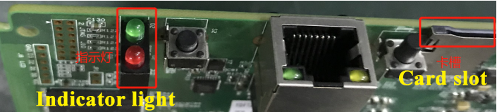
2. For the first time use the 19 series test fixture SD card flash program to the FPGA control board of the tester, copy it to the SD card after decompression, and the SD card the fixture card slot: Power on for about 1 minute, and wait for the red and green indicators on the control board to flash 3 times in succession, then the is complete (if it is not d, it may cause a fixed chip to be reported as defective during the test).

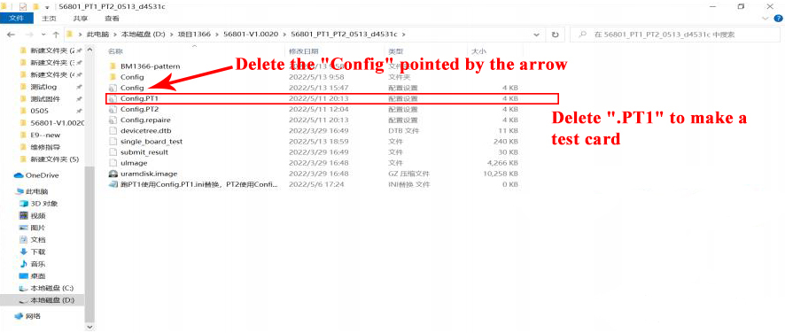
3. Make the SD card according to the requirements. When the hash board is only installed with a single-sided heat sink and detect the chip, directly decompress the compressed package to make the SD card;
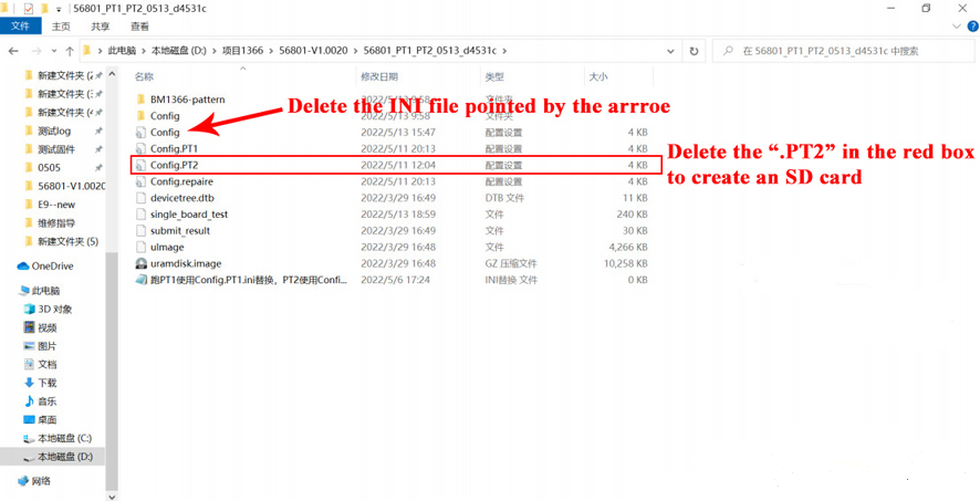
4. Make the SD card according to the requirements, double-sided heat sink, 8 times Parrer test, you need to make the SD card as shown in the figure below:
IV. Principle and Structure of hash board
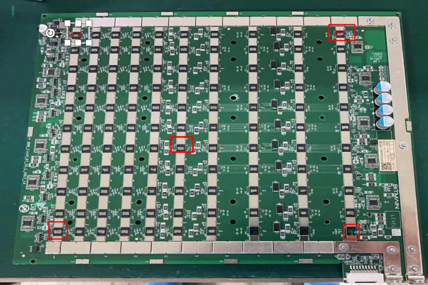
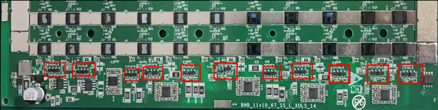
1. Working structure of S19 XP hash board:
The S19 XP hash board is composed of 110 BM1366 chips, which are divided 11 domains, and each domain is composed of 10 ASIC chips.
3. S19 XP chip signal direction:
(1) CLK (OUT) signal flow direction, generated by Y1 25M crystal oscillator, transmitted from chip 01 to chip 110; (0.6-0.7V)
(2) TX (CI, CO) signal flows in from pin 7 (3.3V) of the IO interface, and then transmits from chip 01 to chip 110 after the level conversion IC U10; the voltage is OV when the I0 cable is not ed, and the operation voltage is 1.2V;
.
.
Download, you can view all S19xp hash board repair guides.
As a student of ZMRC crypto miner repair academy, you can download this Bitmain S19xp maintenance tutorial for free.
Click To Obtain