Antminer S19 hash board repair tutorial
-
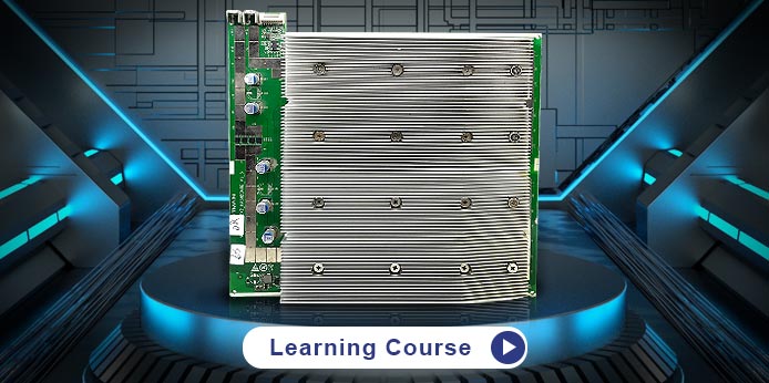 Antminer S19 hash board has a total of 76 BM1398 ASIC chips and is powered by APW12 PSU. The MOS tubes on the S19 hash board is different from the 17 series. The conduction condition of these 4 MOS tubes is that their G-pole input is high level, and they will not play a role in reducing the voltage in the circuit. When the PIC chip is working normally and 3.3V is input, the four MOS tubes will be turned on. Each domain has only one LDO1.8V and PLL 0.8V, and all 0.8V is powered by the LDO1.8V of this domain. Quickly learn how to properly repair an S19 hash board with the Antminer S19 hash board repair tutorial video.
Click To Watch {{ is_submit ? 'View Test' : 'Click To Test' }}-
more
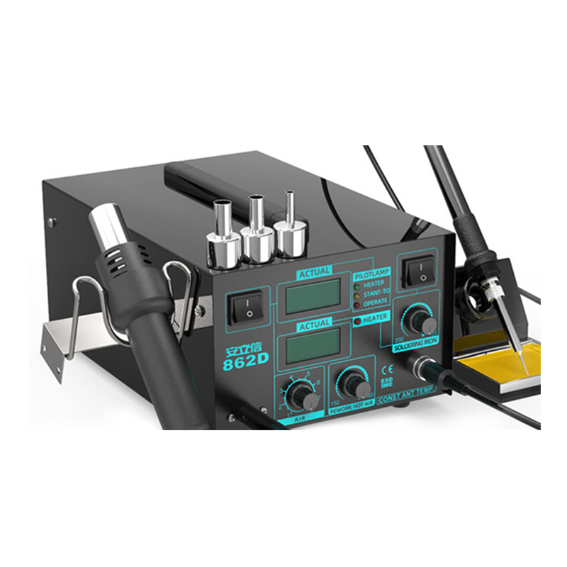
ANLIXIN-862D desoldering station
-
more
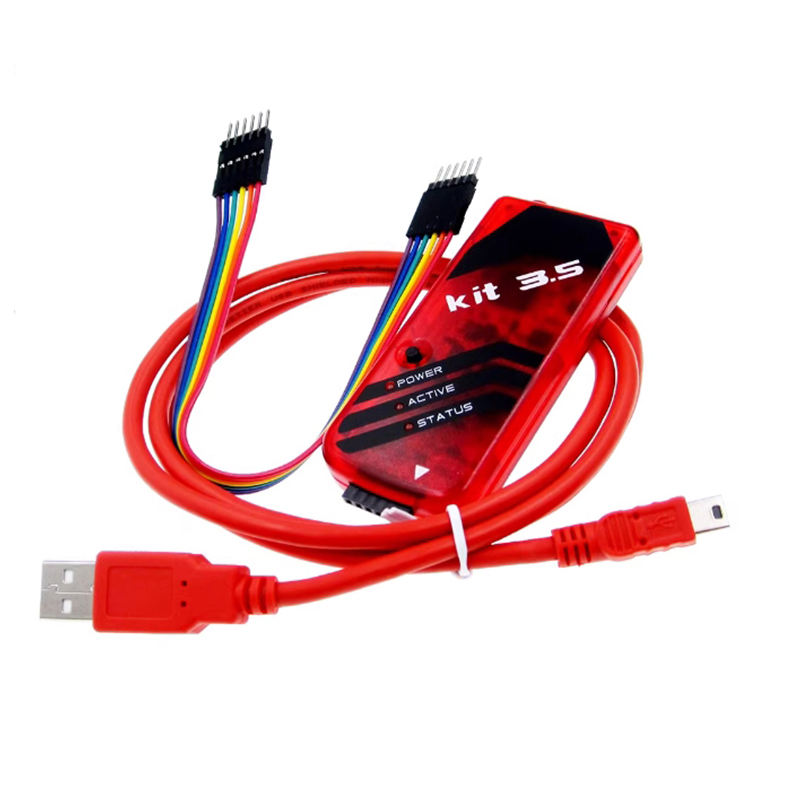
PICKit 3.5 programmer
-
more
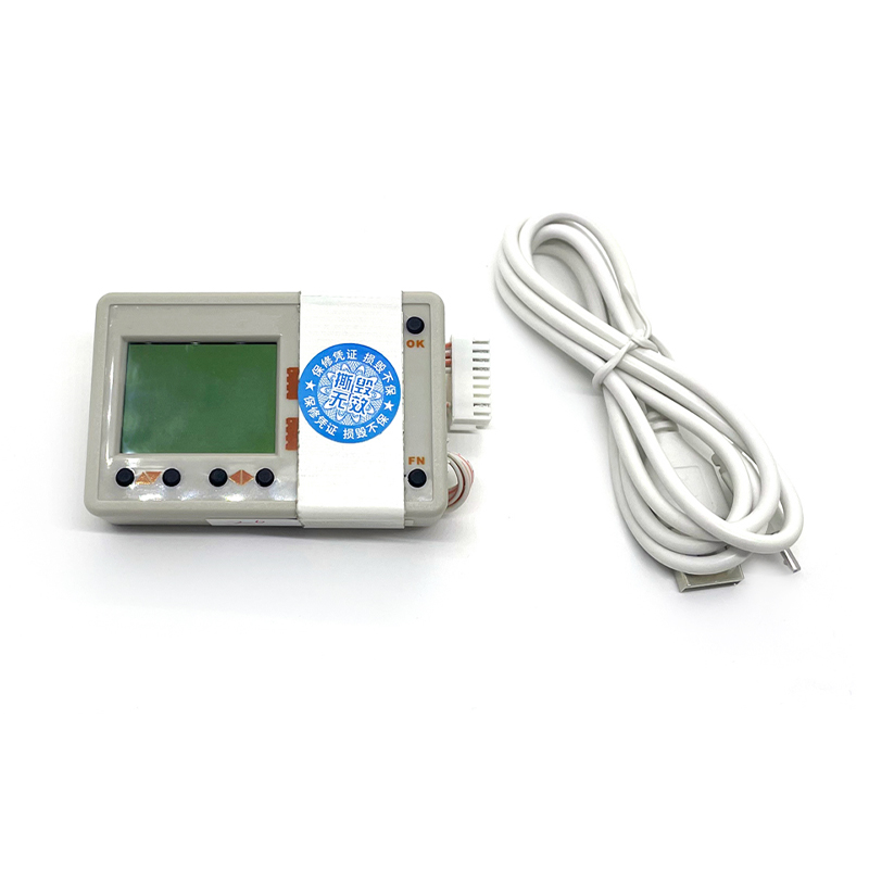
Antminer hash board code editor
-
more
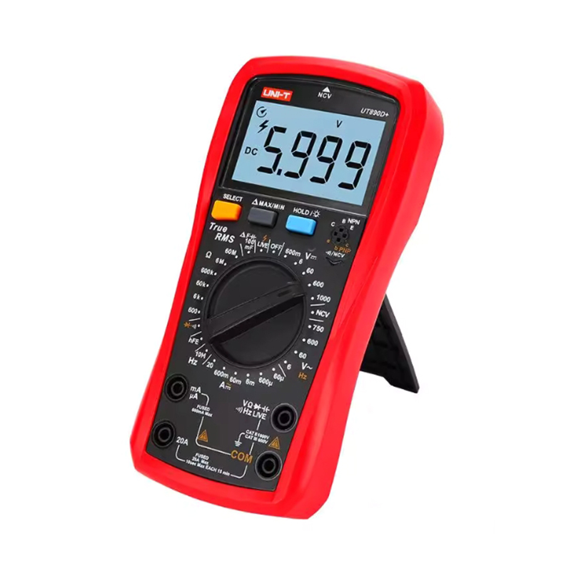
UT890D+ intelligent digital multimeter
-

more
ATTEN lead free solder wire 0.5mm 0.8mm 100g 500g
-
more
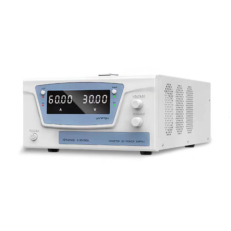
WANPTEK KPS3030D KPS3060D KPS30100D high power DC power supply
-
more
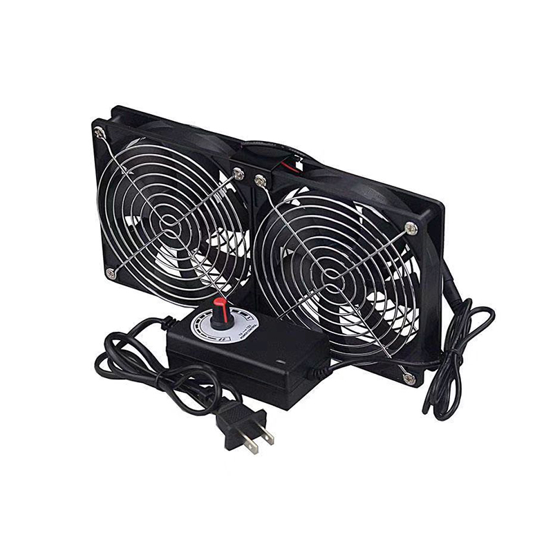
Hash board cooling base 1800RPM
-

more
Amtech NC-559-ASM flux paste 10g 100g
-
more
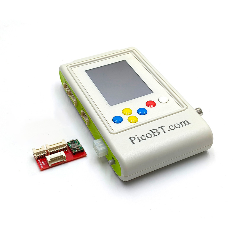
PicoBT Multifunctional Hash Board Tester
-
more
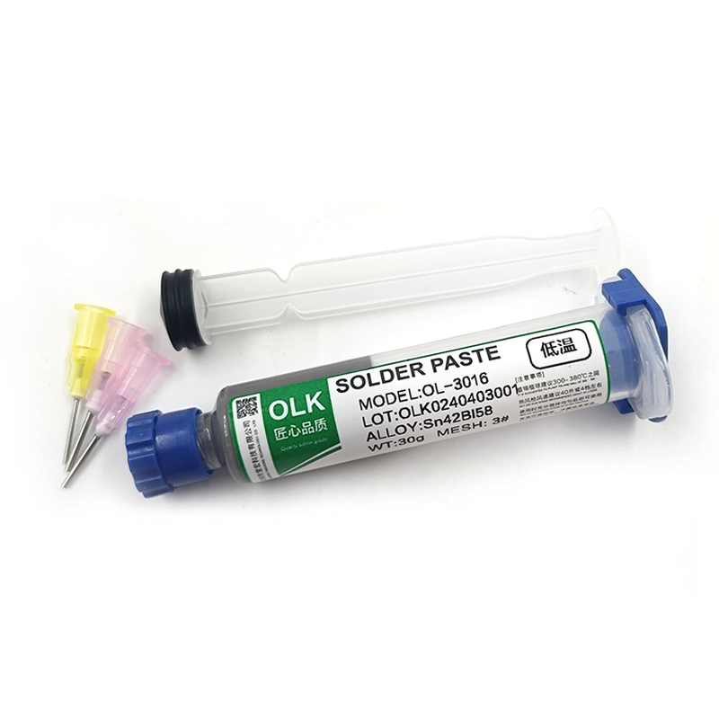
OL-3016 solder paste 138℃ 30g 50g 100g
This training course video is about the Antminer S19 troubleshooting for the hash board's circuit basics and working principles.
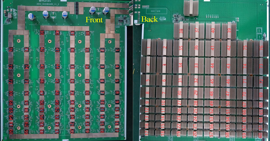
The 76 chips on the Bitmain S19 hash board will perform high-speed hash rate operations. When testing a single board, the test log will display the specific faulty ASIC chip number. It is very important to determine the chip arrangement.
The figure below marks the specific distribution of each ASIC chip on the front and back of the Antminer S19 hash board:
Antminer S19 hash board has 2 boost circuits, the 21V boost circuit is used to turn on the 4 MOS tubes; the 19V boost circuit is used to power the LDO1.8V chips in the last 7 domains. If the powering is abnormal, subsequent LDO1.8V and PPL0.8V may not work properly.
The BM1398 ASIC chip on the S19 hashboard has a total of 5 signals, and their transmission directions are:
CLK signal: No.1 → No.76 ASIC chip
CO signal: No.1 → No.76 ASIC chip
RI signal: No.1 ← No.76 ASIC chip
BO signal: No.1 → No.76 ASIC chip
RST signal: No.1 → No.76 ASIC chip
The ZMRC Antminer repair course will help you remember the S19 hash board structure and working principle, so as to master professional repair skills.
-
{{ item.name }}
Answer: {{ item.answer_txt }}
Analysis: {{ item.analysis }}
Dear Friends,
Hello everyone, as China is about to usher in the Spring Festival, our company is scheduled to start the Spring Festival holiday from February 12 to February 23, 2026 (GMT+8). Our pre-sales customer service and course tutors will reply to your message as soon as possible. Please understand and forgive us if we are unable to reply promptly. Thank you for your support and trust in 2025. In 2026 and the future, the ZMRC team will continue to offer you more professional courses and technical support.
Best wishes,
ZEUS MINING CO., LTD.
CLOSE
